Mechanical Calculation
Summary
In this section, all parameters related to the mechanical calculation of the unit defined in the geometry and the corresponding process conditions for the case under analysis are displayed. Before performing the calculation, it is necessary to finish defining the design parameters of the unit, as well as the design code and the level of non-destructive testing to be used.
Form Fields
These are the fields and UI elements that are shown in this form, along with a describing text and explanation about their usage in the application.
Descriptive name of the heat exchanger
Mechanical Calculation Input Data
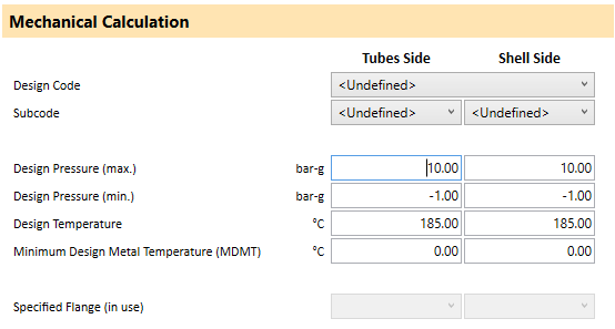
Allows selecting from different design codes supported by AHED.
- PD5500: British Code
- ASME-VIII div. 1: Code developed by the American Society of Mechanical Engineers. It is the standard code in the USA and Canada.
- EN-13445: Mechanic code harmonized with the European Directive (EU). Not yet available
Tube Side
Shell Side
Depending on the mechanical code you have selected, this section takes on a different name, although in all cases it refers to the level of inspection required for the equipment welds.
-
PD5500:
It is divided into 3 categories:
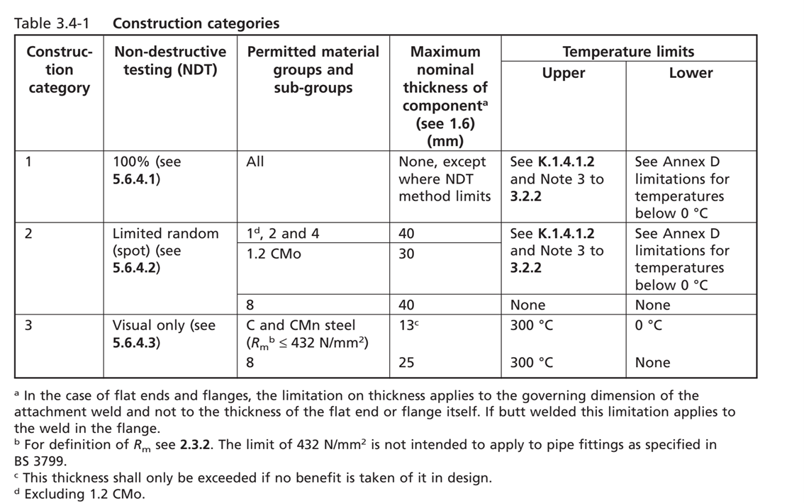 Equipment designed with category 3 only requires visual inspection of the welds, although it will require thicker material and will be limited in
terms of materials and maximum temperature. On the other hand, equipment with category 2 will require a percentage of
inspection of the butt welds using X-ray or ultrasound techniques and inspection of a percentage of the remaining
welds using penetrant liquids. Equipment with category 1 will require a complete inspection using these
techniques, allowing for work with greater material thickness.
Equipment designed with category 3 only requires visual inspection of the welds, although it will require thicker material and will be limited in
terms of materials and maximum temperature. On the other hand, equipment with category 2 will require a percentage of
inspection of the butt welds using X-ray or ultrasound techniques and inspection of a percentage of the remaining
welds using penetrant liquids. Equipment with category 1 will require a complete inspection using these
techniques, allowing for work with greater material thickness.
- ASME VIII Div. 1: ASME has a different classification regarding the equipment inspection level, ranging from RT1 to RT4 or no RT.
- EN-13445: ASME has a different classification regarding the equipment inspection level, ranging from RT1 to RT4 or no RT.
Depending on the mechanical code you have selected, this section takes on a different name, although in all cases it refers to the level of inspection required for the equipment welds.
-
PD5500:
It is divided into 3 categories:
Equipment designed with category 3 only requires visual inspection of the welds, although it will require thicker material and will be limited in
terms of materials and maximum temperature. On the other hand, equipment with category 2 will require a percentage of
inspection of the butt welds using X-ray or ultrasound techniques and inspection of a percentage of the remaining
welds using penetrant liquids. Equipment with category 1 will require a complete inspection using these
techniques, allowing for work with greater material thickness.
- ASME VIII Div. 1: ASME has a different classification regarding the equipment inspection level, ranging from RT1 to RT4 or no RT.
- EN-13445: ASME has a different classification regarding the equipment inspection level, ranging from RT1 to RT4 or no RT.
Maximum design pressure on tube side. It must be greater than 0 and greater than or equal to the operating pressure. This pressure is also used for the calculation of the thickness of the heads.
Maximum design pressure on the jacket side. It must be greater than 0 and greater than or equal to the operating pressure.
Minimum design pressure on tubes. Its value ranges between -1.01325 and 0.
Minimum design pressure on shell. Its value ranges between -1.01325 and 0.
Maximum design temperature on tube side. It must be greater than 0 and will be upper limited based on the design code, chosen test level, or material.
Maximum design temperature on shell side. It must be greater than 0 and will be upper limited based on the design code, chosen test level, or material.
Design minimum temperature on tube side. It can take a value below 0. The limit is generally determined by the type of material.
Design minimum temperature on the shell side. It can take a value below 0. The limit is generally determined by the type of material.
Indicate the rating of flanges on tube side specified in the geometry section. Depending on the chosen rating, the size of the flange changes, which may result in changes to the geometry affecting thermal exchange. For this reason, it can only be modified from the geometry section.
Indicate the rating of flanges on shell side specified in the geometry section. Depending on the chosen rating, the size of the flange changes, which may result in changes to the geometry affecting thermal exchange. For this reason, it can only be modified from the geometry section.
General output data
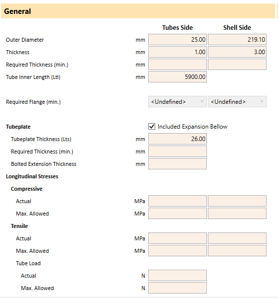
Shows the tubes outer diameter specified in the geometry.
Shows the shell outer diameter specified in the geometry.
Shows the tube side wall thickness specified in the geometry.
Shows the shell thickness specified in the geometry.
Shows the tube side wall required thickness specified in the geometry according to the specified design conditions and design code.
Shows the shell required thickness specified in the geometry according to the specified design conditions and design code.
Tube length measure between inner faces of tubeplates.
Indicates minium flange rating required on tube side according to design conditions.
Indicates minium flange rating required on shell side according to design conditions.
Activate or deactivate the use of the expansion bellows in the heat exchanger.
Thickness specified in the geometry for the tube sheet of the heat exchanger in multitubular exchangers or for the closure of the shell in the case of double-tube exchangers.
Required thickness of tubesheet for multitubular heat exchangers or shell closure for doubletube heat exchangers, under design conditions. AHED always considers an extended as a flange tubesheet for multitubular units, with the shell welded to the tubesheet, and it is not valid for clamp-type or removable pedestals. This thickness is mechanically required, although in some cases, it may need to be increased in the final unit to prevent deformations during the tube welding process. It is recommended, especially with relatively small tubes, that it be at least as thick as the outer diameter of the tube.
This is the minimum required thickness for the screw area of the tubesheet. It is recommended that the thickness of the tubesheet be at least 7mm greater than this value (HRS recommendation).
Maximum compressive stress in the tube. The number of tubes, their thickness, design conditions, and the presence or absence of an expansion bellows affect its value.
Maximum compressive stress in shell side. The thickness of the shell, design conditions, and the presence or absence of an expansion bellows affect this value.
Maximum compressive stress that the inner tube is capable of withstanding. This value should be higher than the calculated maximum stress.
Maximum compressive stress that the shell is capable of withstanding. This value should be higher than the calculated maximum stress.
Maximum tensile stress in the tube. The number of tubes, their thickness, design conditions, and the presence or absence of an expansion bellows affect its value.
Maximum tensile stress in the shell. Shell thickness, design conditions, and the presence or absence of an expansion bellows affect its value.
Maximum tensile strength that the tubes are capable of supporting. This value must be higher than the calculated maximum stress.
Maximum tensile strength that the shell is capable of supporting. This value must be higher than the calculated maximum stress.
The maximum force to which a tube is subjected.
Maximum force that a tube is capable of withstanding. It must be greater than the actual calculated force to which it is subjected.
Nozzles
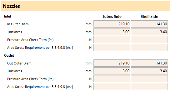
Outer diameter of tube side input nozzle. Specified in the geometry tab.
Outer diameter of shell side input nozzle. Specified in the geometry tab.
Thickness of tube side input nozzle. Specified in the geometry tab.
Thickness of shell side input nozzle. Specified in the geometry tab.
Thickness required according to ASME VIII div 1 UG-45 of tube side input nozzle.
Thickness required according to ASME VIII div 1 UG-45 of shell side input nozzle.
Area of reinformcent of tube side inlet nozzle according to UG-37.1. AHED consider a nozzle an outward nozzle type UW-16.1 (c).
Area of reinformcent of shell side inlet nozzle according to UG-37.1. AHED consider a nozzle an outward nozzle type UW-16.1 (c).
Area of reinformcent required for tube side inlet nozzle according to ASME VIII div 1 UG-37
Area of reinformcent required for shell side inlet nozzle according to ASME VIII div 1 UG-37
Force to which the tube side inlet nozzle is subjected
Force to which the shell side inlet nozzle is subjected
Maximum force the tubes side input nozzle is capable of withstanding. It must exceed the calculated value (Pa). Its magnitude depends on the size and thickness of the body to which it is welded and the size and thickness of the connection itself.
Maximum force the shell side input nozzle is capable of withstanding. It must exceed the calculated value (Pa). Its magnitude depends on the size and thickness of the body to which it is welded and the size and thickness of the connection itself.
Outer diameter of tube side output nozzle. Specified in the geometry tab.
Outer diameter of Shell side output nozzle. Specified in the geometry tab.
Thickness of tubes side output nozzle. Specified in the geometry tab.
Thickness of shell side output nozzle. Specified in the geometry tab.
Thickness required according to ASME VIII div 1 UG-45 of tubes side output nozzle.
Thickness required according to ASME VIII div 1 UG-45 of shell side output nozzle.
Area of reinformcent of tube side outlet nozzle according to UG-37.1. AHED consider a nozzle an outward nozzle type UW-16.1 (c).
Area of reinformcent of shell side outlet nozzle according to UG-37.1. AHED consider a nozzle an outward nozzle type UW-16.1 (c).
Area of reinformcent required for tube side outlet nozzle according to ASME VIII div 1 UG-37
Area of reinformcent required for shell side outlet nozzle according to ASME VIII div 1 UG-37
Force to which the tube side outlet nozzle is subjected
Force to which the shell side outlet nozzle is subjected
Maximum force the tubes side outlet nozzle is capable of withstanding. It must exceed the calculated value (Pa). Its magnitude depends on the size and thickness of the body to which it is welded and the size and thickness of the connection itself.
Maximum force the shell side outlet nozzle is capable of withstanding. It must exceed the calculated value (Pa). Its magnitude depends on the size and thickness of the body to which it is welded and the size and thickness of the connection itself.
Headers
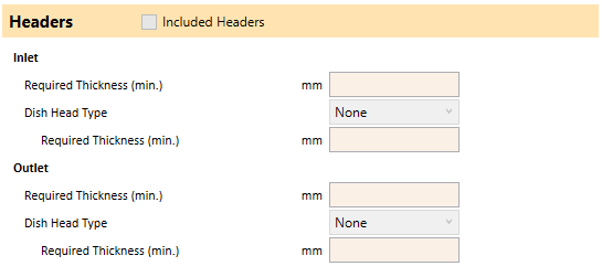
Included Headers
Required thickness for the cylindrical part of the inlet head with the specified design conditions for the tube side
Type of dish end selected for inlet header on geometry tab
Required thickness of dish end of the inlet head with the specified design conditions for the tube side
Required thickness for the cylindrical part of the inlet head with the specified design conditions for the tube side
Type of dish end selected for outlet header on geometry tab
Required thickness of dish end of the inlet head with the specified design conditions for the tube side
Calculate