Geometry
Summary
In this section all the relevant information for defining a heat exchanger's geometry can be introduced. All fields with a white background require user input. Geometries can be defined by either one of the following ways:
- By loading an already made one from the public/shared/personal storage, throuhg File > Manage > Geometry.
- By quick selecting one using the Geometry Presets dropdown list.
- By one of the previous methods, selecting a similar geometry to the one desired, and change it accordingly.
- By introducing all parameters manually.
Form Fields
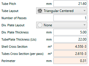
These are the fields and UI elements that are shown in this form, along with a describing text and explanation about their usage in the application.
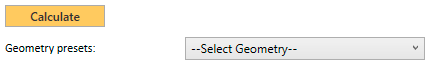
Click on the Calculate button when you have the geometry ready to be calculated by the server. Each click makes an API call to the server. This means that the geometry is sent to the server, calculated there (hence modified) and the results returned back and shown to you. Every calculation increments your license API calls counter.
This is a user-configurable DropDown list of heat exchanger models. You can use it to have the ones you use most at hand. Whenever you select one from the list, the current geometry is replaced with the properties of that heat exchanger model. The list can be customised with your own user-defined models and/or with the models provided by HRS Heat Exchangers as Standards. In order to add/remove models from the list navigate to Tools -> Select Presets -> Geometry Presets.
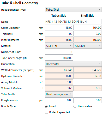
Tube & Shell Geometry
The available options for selecting the type of heat hexchangers are as follows:
- Tube/Shell: Most common type of heat exchanger, composed of two different types of tubes: an inner tube bundle (all equal in diameter) wrapped inside sourounding shell (with a bigger diameter). It can be single pass/multipass, with/whithout baffles, etc.
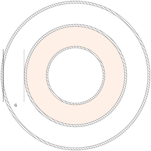
- Annular Space: A particular type of heat exchanger where 3 different concentric tubes are inserted one into the other. The product moves along the chamber made by the inner and sencond tube. The service is moved along the inner tube and the space between the outer shell and the second tube. The product is therefore heated or cooled from both sides.
- Unicus: A type of Scraped Surface Heat Exchanger (SSHE) in which the scraping elements move along the tubes, forth and back, following a linear movement.
- R Series: A type of Scraped Surface Heat Exchanger (SSHE) in which the scraping elements move around the inner section of the tubes, following a rotary path.
Tube Side
Shell Side
Name 🇦
Descriptive name of the heat exchanger. Its value is automatically changed to follow the properties of the geometry as it calculated and/or modified.
External diameter of the tubes used in the tube bundle. Please note that for monotubes, it will be the size of the single inner tube, but for multitubular heat exchangers this figure will be the diameter used for all tubes inside it.
External diameter of the shell of the heat exchanger. No matter what heat exchanger type is selected, this figure will always be the outer diameter of the largest external tube, commonly referrered to as the shell.
Thickness of the tubes used in the tube bundle.
Thickness of the shell.
Read-Only. Inner diameter of the tubes used in the tube bundle. It is automatically calculated from the outer diameter minus two times the thickness.
Read-Only. Inner diameter of the shell. It is automatically calculated from the outer diameter minus two times the thickness.
Select one of the predefined materials available for the tubes: AISI 304, AISI 316L, DUPLEX, SUPERDUPLEX and Titanium. Each of these well-known materials has its own thermal conductivity properties built-in into the program and used accordingly.
Select one of the predefined materials available for the shell: AISI 304, AISI 316L, DUPLEX, SUPERDUPLEX and Titanium. Each of these well-known materials has its own thermal conductivity properties built-in into the program and used accordingly.
This field is used to declare the number of tubes that you want to use inside the heat exchanger. After performing the geometry calculations, if these tubes do not fit into the shell, the number is decreased to the maximum number of tubes that fits. A warning message is shown to the user in this case, meaning that the desired number of tubes was not achieved and needed to be a lesser number. If no other warning messages are shown and the same calculation is done a second time, it should end successfully without any warning (since the desired number of tubes is not modified again server-side).
The length of the tubes measured from the inside of the shell, i.e. not taking into account the thickness of both tubeplates. This length is the effective length where the heat transfer takes place. There is no heat transfer performed during the transit within both headers since there is no fluid at the other side of the tubes along those points.
The orientation of the heat exchanger can be either horizontal or vertical. Horizontal heat exchangers are the default option but sometimes due to space requirements they are required to be installed vertically. Depending on your selection, different heat transfer coefficients may result in the overall calculation, mainly due to different formulas being used in the evaluation of the Reynolds and Nusselt numbers when using a condensing fluid in the shell side.
Read-Only. The Wetted Perimeter is defined as the perimeter of the cross sectional area that is "wet", meaning in contact with the tube's product. For the usual Shell&Tube heat exchangers it is defined as π × Tube Inner Diameter × Number of Tubes / Number of Passes. Other formulas are used for the different types of heat exchangers.
Read-Only. The Wetted Perimeter is defined as the perimeter of the cross sectional area that is "wet", meaning in contact with the shell's service fluid. For the usual Shell&Tube heat exchangers it is defined as (π × Shell Inner Diameter) + (π × Tubes Outer Diameter × Number of Tubes). Other formulas are used for the different types of heat exchangers.
Read-Only. The Hydraulic Diameter, DH, is a commonly used term when handling flows in non-circular tubes and channels. Using this term, one can do calculations for the whole tube bundle in the same way as for an equivalent single round tube. It is defined as 4 × Cross Section Area / Wetted Perimeter.
Read-Only. The Hydraulic Diameter, DH, is a commonly used term when handling flows in non-circular tubes and channels. Using this term, one can do calculations for the shell flow (considering it has the tubes inserted within) in the same way as for an equivalent single round tube. It is defined as 4 × Cross Section Area / Wetted Perimeter.
Read-Only. Heat Transfer Area per heat exchanger module. For the usual Shell&Tube heat exchangers it is defined as π × Tubes Outer Diameter × Tubes Length × Number of Tubes. Other formulas are used for the different types of heat exchangers.
Read-Only. Volume of tube's fluid per heat exchanger module. This volume does not consider inlet/outlet nozzles nor volume along the headers (tubeplates). It is only the volume subject to heat transfer, i.e. volume of tube's product that has contact with the shell's service.
Read-Only. Volume of shell's fluid per heat exchanger module. This volume does not consider inlet/outlet nozzles nor volume along the headers (tubeplates). It is only the volume subject to heat transfer, i.e. volume of shell's service that has contact with the tube's product.
You can select either Hard corrugation or Smooth tubes. Better heat transfer coefficients at a slightly higher pressure drop are achieved with corrugated tubes. However certain applications and models require smooth tubes to be used too.
Usual values are: <0.5μm for pharma tubes, <0.8μm for food-grade tubes and >0.8μm for industrial tubes. Default value 0.8μm. The roughness of the tubes is used to calculate Darcy Friction Factor and the pressure drop.
Usual values are: <0.5μm for pharma tubes, <0.8μm for food-grade tubes and >0.8μm for industrial tubes. Default value: 0.8μm. The roughness of the shell is used to calculate Darcy Friction Factor and the pressure drop.
Scraping speed of the Dynamic Heat Exchanger (in rpm), both used for U-Series and R-Series models. For the R-Series, the maximum allowed values are as follows:
| Engine Power / Max. Freq. | 4kW | 7.5kW | 15kW | 30kW |
|---|---|---|---|---|
| R1 Series | 268rpm | 306rpm | N/A | N/A |
| R3 Series | N/A | N/A | 351rpm | 350rpm |
Motor Power of R-Series Dynamic Heat Exchangers models. Valid values are as follows:
| Engine Power | 4kW | 7.5kW | 15kW | 30kW |
|---|---|---|---|---|
| R1 Series | ● | ● | ||
| R3 Series | ● | ● |
Use this option when fixed tubeplate are to be used. This results in more compact heat exchangers since they do not require to have higher Minimum Tube Hole To Tubeplate Edge (D) and Tubeplate To Shell (B) values. When using this option, multipass heat exchangers can also be calculated, which is a restraint for removable bundles (they need to be single pass).
When dismountable heat exchangers are needed, this option needs to be set. When used, certain restrictions apply:
- Multipass heat exchangers cannot be dismountable (this checkbox must be cleared) or, in other words, when a removable bundle is required the resulting heat exchanger must be single-pass.
- Removable bundles require to have higher Minimum Tube Hole To Tubeplate Edge (D) and Tubeplate To Shell (B) in order for the seals around the tubeplate and their housings to have space.
When roller expanded tubes are used, the minimum pitch for the tubeplate increases from 1.2 times the outer diameter of the tubes to 1.25 times. For example, when using non-roller expanded 18 mm. tubes, the pitch can be as low as 21.6 mm. However when this option is active, the minimum pitch is increased to 22.5 mm. Roller expanded tubes are not used by default.
Nozzles
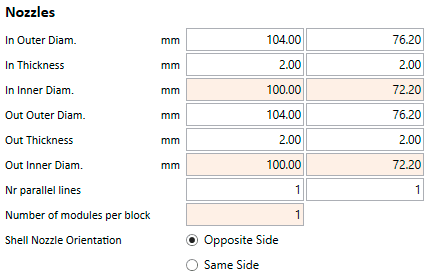
Outer diameter of the inlet nozzle for the tubes.
Outer diameter of the inlet nozzle for the shell.
Thickness of the inlet nozzle for the tubes.
Thickness of the inlet nozzle for the shell.
Read-Only. Inner diameter of the inlet nozzle for the tubes. Calculated.
Read-Only. Inner diameter of the inlet nozzle for the shell. Calculated.
Outer diameter of the outlet nozzle for the tubes.
Outer diameter of the outlet nozzle for the shell.
Thickness of the outlet nozzle for the tubes.
Thickness of the outlet nozzle for the shell.
Read-Only. Inner diameter of the outlet nozzle for the tubes. Calculated.
Read-Only. Inner diameter of the outlet nozzle for the shell. Calculated.
Number of parallel lines to be connected through the tubes nozzles.
Number of parallel lines to be connected through the shell nozzles.
Read-Only. Number of Heat Exchanger Modules that will be necessary to configure a block with the declared Nozzle Parallel Lines for Tubes and Shell. The following table illustrates some of the trivial and most simple cases, as the number of parallel lines increases, this number is more complex to calculate (not necessarily higher).
| Nozzle Parallel Lines | Shell | ||||||
| 1 | 2 | 3 | 4 | 5 | 6 | ||
|---|---|---|---|---|---|---|---|
| Tubes | 1 | 1 | 2 | 3 | 4 | 5 | 6 |
| 2 | 2 | 2 | 6 | 4 | 10 | 6 | |
| 3 | 3 | 6 | 3 | 12 | 15 | 6 | |
| 4 | 4 | 4 | 12 | 4 | 20 | 24 | |
| 5 | 5 | 10 | 15 | 20 | 5 | 30 | |
| 6 | 6 | 6 | 6 | 24 | 30 | 6 | |
Check this option when the inlet and outlet nozzles are positioned opposite sides of the heat exchanger. This is a critical parameter when baffles are used, since the position (same or opposite) of the inlet and oulet nozzles determine the number (odd or even) of baffles that can be positioned inside the heat exchanger. When this option is used (they are on opposite sides), the number of baffles used (if any) must be even.
Check this option when the inlet and outlet nozzles are positioned the same side of the heat exchanger. This is a critical parameter when baffles are used, since the position (same or opposite) of the inlet and oulet nozzles determine the number (odd or even) of baffles that can be positioned inside the heat exchanger. When this option is used (they are on the same side), the number of baffles used (if any) must be odd.
Tubeplate Layout
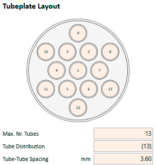
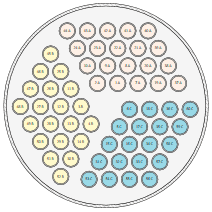
When a valid geometry is calculated, a cross section drawing of the tubeplate is shown, with an accurate representation of all its components, relatives sizes and positions. This drawing includes the following elements:
- the shell, with proper size and thickness,
- the tubes' distributions and positions,
- division plates (if any),
- inner tube (in Annular Space Heat Exchangers)
- scraping elements (in R & U Series)
- colour-coded tube distribution (in multipass heat exchangers)
Double clicking on the drawing, opens a new standalone window with only this image. This new window can be maximized, zoomed-in, etc. for detail checking. The user can even select which tubes will or will not be used by double clicking on each tube.
Read-Only. This figure shows the maximum amount of tubes that would fit inside the Shell for the given configuration, considering Shell Inner Diameter, Tubes Outer Diameter, Tube Pitch, Tube Layout, Number of Passes, etc. as well as any other paramter in the Clearances & Spacing section.
If the user performs a calculation trying to use a Number of Tubes higher than this calculated value, the results will finish with a Warning, since it was impossible to met the the original requirements (and the number of required tubes had to be reduced down to this figure).
Read-Only. This field is a comma separated list of values, showing how many tubes will be placed inside each one of the passes.
For single pass heat exchangers this list will contain a single figure equal to the Number of Tubes.
For multipass heat exchangers the list will contain as many numbers as the number of passes, and the sum of them will be equal to the Number of Tubes. The number of tubes belonging to each pass should be equal for all passes for a heat exchanger to be considered a good multipass solution. In other words, it should have all its passes balanced. Unbalanced solutions however are also allowed up to a certain point, but results will be shown with a Warning.
Every pass will always require a miniumum of a tube. There cannot be passes without tubes. Obviously, trying to calculate a heat exchanger with more passes than tubes will result in an Error.
Read-Only. Shows the minimum distance between two neighbour tubes. It is equal to the Tube Pitch - Tubes Outer Diameter. Calculated.
The Tube Pitch is the shortest center-to-center distance between tubes. The Tube Spacing is given by the Tube Pitch / Tubes Outer Diameter ratio, which is by default 1.2 (and increases to 1.25 when roller expanded tubes are used).
The user can increase this value so that bigger spaces (and less tubes) are used when calculating the tubeplate, but never change it below the default value. The default value will always return solutions with the highest density of tubes.
If the user sets this value to 0 and launches a calculation, the server will reset it to the default (minimum) value. This feature can be used to avoid the calculation of the pitch manually, leaving that task to the server. Any other value different than 0 will be considered as valid and an Error will raise if it is below the required minimum value.
There are 6 different tube layouts available, plus an additional option to automatically select the one that fits more tubes (optimum solution):
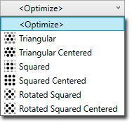
- <Optimize>
- Triangular
- Triangular Centered
- Squared
- Squared Centered
- Rotated Squared
- Rotated Squared Centered
Triangular and Triangular Centered always return the maximum density of tubes (optimum solution) for single pass heat exchangers. However, when multiple passes are needed and division plates used, the optimum solution is not always the same.
Number of Passes governs the multipass calculations. When set to 1 the calculated heat exchanger will be a single pass heat exchanger, and the Division Plate Layout can only be None. Different Number of Passes enable different types of Division Plate Layouts, and also where the inlet & outlet of the tubes side are placed. For even number of passes the produce in the tubes section enters and exits from the same side. When odd number of passes are required, it does from opposite sides.
Depending on the Number of Passes there are different options available:
- 1 Pass: None
- 2 Passes: Horizontal, Vertical & Mechanised
- 3 Passes: Horizontal, Vertical & Mechanised
- 4 Passes: Horizontal, Horizontal+Vertical & Mechanised
- 5 Passes: Horizontal & Mechanised
- 6 Passes onwards: Mechanised
Sealing Type is only available when Division Plate Layout is Mechanised. The available options are O'Rings + Housings and Gasket.
Read-Only. Housings Space is the space left for placing the housings for the O'rings that will be used to seal each pass inside each of the headers of the heat exchanger. It is automatically calculated and it is a requiriment that it will be at least twice (2x) the amount of Minimum Tube Hole To Tubeplate Edge (D) in order to be able to place two O'rings around the tubes of each pass to isolate them from adjacent passes.
The algorithm first performs a normal tubeplate calculation trying to place all the tubes using the required Tube Pitch and Tube Layout. In a second step the passes are calculated, trying to distribute the tubes equally among each pass. In the last step, the tubes belonging to each pass are moved together towards the edge of the tubeplate, in order to make room for the housings.
In this last step, it might be needed to remove some of the tubes in the outer rings so that the required Housings Space is achieved. One requirement for the algorithm to be able to perform this last step is that the centroids of each pass must be all equidistant from the center of the tubeplate. If the tube distribution is not following a regular pattern, or the passes do not have all the same number of tubes, chances are that the algorithm is not able run this last step and calculate the Housing Space.
In multipass heat exchangers not using a Mechanised header, division plates must be used in one (or both) headers so that the produce through the tubes is conducted through the right tubes (following the right distribution). Division Plate Thickness has a default value of 5 mm.
Tubeplate Thickness (Lts) parameter is used when displaying the side view (in Baffles section) in order to give the tubeplate a width (it should not be zero). It does not serve any other purpose in the calculations than this visual aestetic function, since the actual heat transfer length is the Tube Inner Length (Lti)
Read-Only. Shell Cross Section is the area inside the shell taking into account that it is filled with tubes. It is based on the formula A = π × r2, considering r as the Shell Inner Diameter, and then substracts the area formed by the Number of Tubes inside the shell. For Annular Space Heat Exchangers, it combines (add) the extra shell area inside the innermost tube. Calculated.
Read-Only. Tubes Cross Section is the sum of areas inside the tubes. It is based on the formula A = π × r2, considering r as the Tubes Inner Diameter, multiplied by the Number of Tubes used and divided by the Number of Passes. For Annular Space Heat Exchangers, it substracts the area used by the inside the innermost tube. Calculated.
Read-Only. The Perimeter of the tubeplate, by simply calculating P = 2 × π × r, where r is the Shell Inner Diameter. Calculated.
Parallel Lines Distribution Diagram (per block)
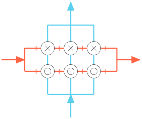
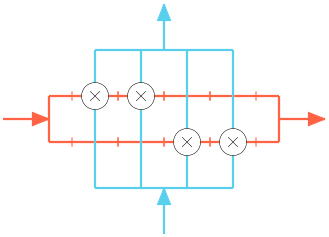

Diagram 📈
A sketch of the general layout of heat exchanger modules composing a block is shown here. It has into consideration not only the number of Nozzle Parallel Lines for both Tubes and Shell, but also the number of passes too.
1 parallel lines in tubes x 1 parallel lines in shell, using single pass heat exchangers.
1 parallel lines in tubes x 1 parallel lines in shell, using multipass (4) heat exchangers.
3 parallel lines in tubes x 2 parallel lines in shell, using single pass heat exchangers.
4 parallel lines in tubes x 2 parallel lines in shell, using single pass heat exchangers.
5 parallel lines in tubes x 1 parallel lines in shell, using single pass heat exchangers.
The symbols × and ○ inside each shell show the direction of each pass, × meaning the flow inside the tubes is going away from the viewer, whereas ○ is used when the flow in the tubes goes towards the viewer. For multipass heat exchangers, several of these symbols are used, one for each pass, alternatively. When multiple heat hexchanger modules are required, those symbols are also used alternatively to show the direction of the flow in the tubes for each heat exchanger.
Clearances & Spacings
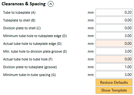
Tube to Tubeplate (A) is the distance from each tube to the inner side of the hole in the tubeplate that holds it within. When set to 0, the tubes are fully in contact with the tubeplate, without any margin. This is not usually done since certain tolerances are allowed. This value defaults to 0.2 mm. which means that, when a tube is inserted inside its tubeplate hole, there will be a tolerance of 0.1 mm. between each side of the tube and the tubeplate hole, which will be slightly bigger.
Tubeplate to Shell (B) is the distance from the tubeplate to the inner side of the shell (inner diameter). When set to 0, the tubeplate is fully in contact with the shell, without any margin. This could be a problem when using big shell sizes, due to irregularities in the shell (not being a perfect circle). This parameter can be used to allow a certain tolerance. It defaults to 0, meaning that there will be no tolerance between the outer side of the tubeplate and the inner side of the shell.
Division Plate to Shell (C) is the tolerance to be considered for the edge of any division-plate to the inner side of the shell. Half of this amount is assigned to each side of the division-plate. This parameter is not used at all in single pass heat exchangers or multipass with mechanised headers.
Minimum Tube Hole to Tubeplate Edge (D) is the minimum distance to the edge that a tubehole in the tubeplate can be. This value defaults to 3 mm. for heat exchangers with Fixed tube bundles. When Removable tube bundles are used, this value increases to 4 mm. Lower values are not allowed due to constructible problems (deformations) that might arise during the welding of the tubes if smaller values were used.
Read-Only. Actual Tube Hole to Tubeplate Edge (D) is the distance from the outmost tubehole to the edge of the tubeplate. This is a read-only value since it is calculated from the actual values of the tubeplate once it has been fully calculated. If, once the tubeplate is calculated, this value is bigger than Minimum Tube Hole to Tubeplate Edge (D) an error will be shown.
Minimum Tube Hole to Division Plate Groove (E) is the minimum distance that a tube hole must have to any of the grooves in the tubeplate. In multipass heat exchangers with division plates, in order for the tubeplate to hold the division plates, grooves are made along the division plates' positions. No tube hole must be placed nearer than this minimum value so that the heat exchanger could be constructible. Otherwise there would be no space for welding the tubes or the actual division plates. This value defaults to 3 mm.
Read-Only. Actual Tube Hole to Tube Hole (F) is the minimum distance from any two adjacent tube holes in the tubeplate. It refers to the actual tubeplate once it is calculated and the value is equal to: Tube Pitch - Tube Outer Diameter - 2xTube to Tubeplate (A). This value cannot be smaller than the constant MINIMUM_TUBEHOLE_TO_TUBEHOLE set internally to 2.2 mm. or an error will be shown accordingly.
Division plate to tubeplate (groove) is the extra space that the groove in the tubeplate must have with regard the division plate thickness. It defaults to 1 mm. so that there will be 0.5 mm. of extra space around any side of the division plates. This space is needed for both tolerance and welding.
Minimum Tube In Tube Spacing (G) is only used in Annular Space Heat Exchangers and refers to the minimum free space that can be left between two concentric tubes, either between the shell and the first tube, or between the first tube and the inner tube. If any of these requirements are not met, an error is shown accordingly.
Restores the default values the Clearances & Spacing section, depending on the parameters of the heat exchanger being designed different default values apply. For instance Multipass Heat Exchangers with Mechanised Headers have different defaults than others. Globally, the criteria that govern the default values are the Heat Exchanger Type, the Bundle Type (fixed or removable), the Tube Outer Diameter and the Number of tubes
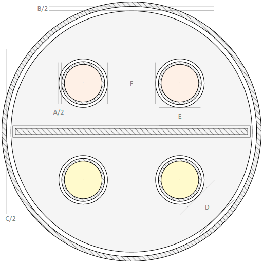
Opens a pop-up window with the default tubeplate template for the selected type of heat exchanger. Useful to see graphically all the parameters in the Clearances & Spacing section.