Baffles
Summary
In this section all the relevant information for defining a heat exchanger's baffles configurations can be introduced. All fields with a white background require user input. Baffles are usually optional but, under certain circumstances, a minimum amount of support baffles are required. Despite of being in a different section, Baffles are part of a Geometry and as such, they are saved/loaded along with a Geometry preset (or personal).
Form Fields
These are the fields and UI elements that are shown in this form, along with a describing text and explanation about their usage in the application.
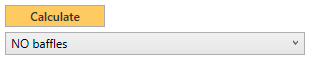
Click on the Calculate button when you have the baffles parameters ready to be calculated by the server. Each click makes an API call to the server. This means that the geometry and baffles set up is sent to the server, calculated there (hence modified) and the results returned back and shown to you. Every calculation increments your license API calls counter.
The available options for selecting the type of Baffles are as follows:
- NO Baffles: When no extra turbulence is needed, when the heat exchanger is short enough or when the fluid velocity / heat transfer achieved is enough there is no need to use baffles. Select this option for these cases. No extra API calls are required when there are no baffles to calculate.
- Standard heat transfer with SUPPORT baffles only: When the length of the heat exchanger is long enough, it requires at least to have support baffles. Take into account that, despite the fact that baffles in this configuration create extra turbulence, higher pressure drop and better overall heat transfer, none of these extra calculations are performed. If the Number of Baffles is left as 0, the calculation automatically assigns the Inlet baffle spacing (Lbi), the Outlet baffle spacing (Lbo) and the minimum Number of baffles to comply with TEMA requiements. The ususal values are: 4 baffles for heat exchangers up to 2m. 6 baffles for lengths up to 3m., and 12 baffles for 6m. lengths.
-
FULL baffles heat transfer calculation: When baffles are used using this configuration, all extra calculation steps regarding the Bell-Delaware Method for baffle and pressure
drop calculation are performed. As a result, the correction factors:
- Jc = correction factor for baffle window flow or baffle cut effect,
- Jl = correction factor for baffle leakages effects,
- Jb = correction factor for bundle bypass effects or recirculation flow effect,
- Jr = laminar flow correction factor or adverse temperature gradient,
- Js = correction factor for unequal/uneven baffle spacing
- Ji = Colburn correction factor
Basic Baffle Geometry Relations
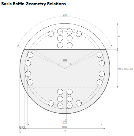
Whenever the tubeplate and baffles are not calculated a templated is shown, to illustrate the names of variables, their placements and overall organization. After the Geometry and/or baffles are calculated the templated image is removed and a more accurate image, representing the baffle is shown.
Baffle Geometry Parameters
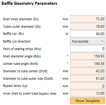
Read-Only. This field with the Shell Inner Diameter (Ds) is show here just for convenience. If you ever need to modify it, you need to do it from the Geometry page, where this value is taken from.
Read-Only. This field with the Tubes Outer Diameter (Dt) is show here just for convenience. If you ever need to modify it, you need to do it from the Geometry page, where this value is taken from.
The practical range of Baffle Cuts is from 15 to 45% with a default value for new Geometries of 40%
The Baffle Cut Direction is selected to be Horizontal when the baffles are placed alternatively up and down along the heat exchanger. When the Baffle Cut Direction is Vertical, they are placed to the inner left and right sides of the heat exchanger. In the latter case the heat exchanger is more easily drawnable. When the Baffles have Bypass Lanes, it is recommended that those lanes are orientated perpendicular to cross flow.
Sealing Strips are used to minimise the channeling of fluid between the outer row of tubes and the shell. They usually consist of metal strips fit into slots in the baffles and extend outward toward the shell wall to block the bypass flow and force it back into the tube bundle. They are placed in pairs on opposite sides of the baffles runing lengthwise along the bundle. Sealing Strips are usually used in floating-head exchangers, where the clearance between the shell and the tube bundle is relatively large. Tipically, one pair is used for every four to ten rows of tubes between the baffle tips.
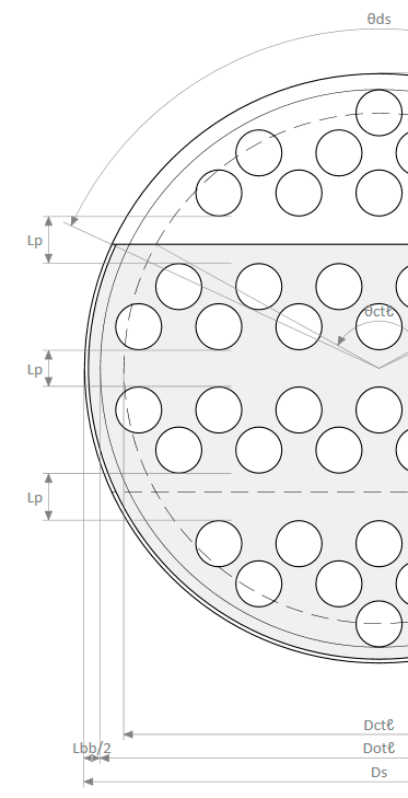
Read-Only. The angle θds is directly calculated based on Baffle Cut percentage (Bc) through the formula
θds = 2 · cos-1·(1 - 2 · Bc)
Read-Only. Simmilarly to θds, the angle θctℓ is determined by the Baffle Cut percentage (Bc), the Shell Inner Diameter (Ds) and the Diameter to Tube Center (Dctℓ) according to the formula
θctℓ = 2 · cos-1·[Ds · (1 - 2 · Bc) / Dctℓ]
Read-Only. The central tube diameter, Dctℓ, is the diameter of the circle that passes through the centers of the outermost tubes in the bundle and is defined as Dctℓ = Dotℓ - Dt
Read-Only. The Diameter to Tube Outer Side (Dotℓ), outer tube limit diameter or bundle diameter is the diameter of the circle that inscribes all the tubes in the bundle.
Bypassing occurs where fluid from the crossflow stream avoids flowing through the tube bundle and is caused by the existence of alternative, low resistance flow routes.
There are several causes of bypassing. The commonest is due to the unavoidable manufacturing clearance between the shell and the tube bundle, which in the case of pull-through floating head types may be relatively large, as there must be a clearance to allow one tubesheet to be withdrawn through the length of the shell. The effects of this type of bypassing can be reduced by inserting sealing-strips between the tube bundle and the shell-wall to block the gap. Sealing strips are sheet metal strips which are attached to the baffles and force the bypass stream back into the tube bundle.
Another type of bypassing is the deliberate use of access lanes created by removing one or more rows of tubes. This is particularly common in power condensers where they are used to prevent air blanketing of the tubes by increasing the flow velocity. This results in an increase in heat transfer.
The bypass lane, however it is formed, is a route of relatively low resistance to the flow. Therefore, even in cases where the bypass area is small in relation to the overall flow area, a relatively, large proportion of the flow will pass through it. Where the bypass lane is formed next to the shell wall it leads to a reduction of heat transfer as the shell of the exchanger is not a heat transfer surface.
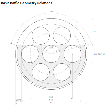
Bypass Lanes can also be geometrically forced due to division plates used in multipass heat exchangers because of the extra space they need in both headers. See the three bypass lanes tagged Lp in the image from a 4-passes heat exchanger with 3 horizontal division plates. In this case, the Bypass Lane field would show
{H15.72, H12.2, H15.72}
meaning that there are three Horizontal
bypass lanes of 15.72, 12.2 and 15.72mm witdh (height in this case, since they are all horizontal).
The Bypass Lanes field is only calculated when FULL baffles heat transfer calculation is selected. An ideal bundle does not have any bypass lane. When present, it is recommended that they are orientated perpendicular to cross flow.
Read-Only. The Inner Shell to Outer Tube Bypass Clearance (Lbb) is defined as the distance between Dotℓ and the inner side of the shell, thus its value results from the formula
Lbb = Ds - Dotℓ
When the Baffles for a particular Geometry are calculated, the displayed image is no longer the template. If you need to check the default template image for the baffles (the one used for new empty Geometries), you can click on this button.
Baffle Distribution
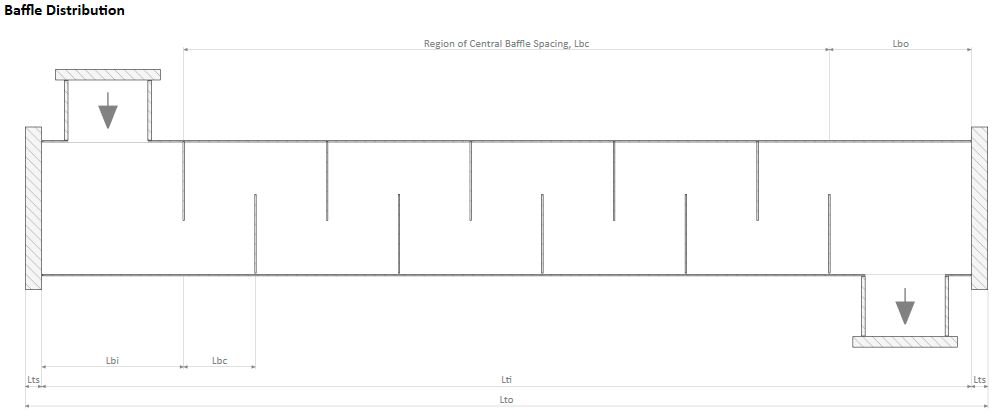
Whenever the tubeplate and baffles are not calculated a templated is shown, to illustrate the names of variables, their placements and overall organization. After the Geometry and/or baffles are calculated the templated image is removed and a more accurate image, even a faithful aspect ratio among height and length of the heat exchanger.
Baffle Distribution Parameters
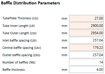
Read-Only. This field is shown here for convenience. It takes its editable value from the the TubePlate Thickness (Lts) field in the Geometry page. This is a value that has to be added twice (one for each header) to the Tube Inner Length (Lti) in order to calculate the Tubes Outer Length (Lto), that could be taken as the total length of the heat exchanger (without bends or interconnections).
Read-Only. Shown for convenience from the actual value in Tube Inner Length (Lti) field in the Geometry page.
Read-Only. Calculated value resulting from the sum of twice the Tubeplate Thickness (Lts) plus the Tubes Inner Length (Lti).
Inlet Baffle Spacing (Lbi) is the distance from the edge of the tubeplate to the first baffle, in the shell inlet side. The minimum value for Lbi is calculated according the following equation:
Read-Only. Central Baffle Spacing (Lbc) is the distance between any pair of adjacent baffles, resulting from the formula
Lbc = (Lti - Lbi - Lbo - (Nb * BaffleThickness)) / (Nb - 1)
Outlet Baffle Spacing (Lbo) is the distance from the last baffle to the edge of the tubeplate, in the shell outlet side. The minimum value for Lbi is calculated according the following equation:
Number of Baffles (Nb) has to be an even number when Shell Nozzle Orientation is set to Opposite Side. When both nozzles are placed on the Same Side the number of baffles must be odd.
Baffle Thickness defaults to 4mm. When left as 0, the calculation process automatically (if possible) sets this value to the standard values for Baffle Thickness in Class R Heat Exchangers, as in Table 5.2 of the book Process Heat Transfer. Principles and Applications (Serth, 2007). See also Table R-4.41 - Baffle or Support Plate Thickness of TEMA Standards. Class R calls for heavier and more conservative construction features, than Classes B and C. The resulting automatic value depends on the Shell inner diameter and Central baffle spacing.
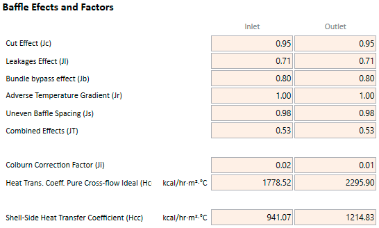
Baffle Effects and Factors
Inlet
Outlet
Read-Only. Only visible when FULL baffles heat transfer calculation is selected. Inlet Baffle Cut Effect (Jc) is the correction factor for baffle window flow at the inlet.
The factor Jc accounts for heat transfer in the baffle windows. It has a value of 1.0 for exchangers with no tubes in the windows. For other exchangers, it ranges from about 0.65 for very large baffle cuts to about 1.15 for small baffle cuts. For well-designed exchangers, the value of Jc is usually close to 1.0.
Read-Only. Only visible when FULL baffles heat transfer calculation is selected. Outlet Baffle Cut Effect (Jc) is the correction factor for baffle window flow at the outlet.
The factor Jc accounts for heat transfer in the baffle windows. It has a value of 1.0 for exchangers with no tubes in the windows. For other exchangers, it ranges from about 0.65 for very large baffle cuts to about 1.15 for small baffle cuts. For well-designed exchangers, the value of Jc is usually close to 1.0.
Read-Only. Only visible when FULL baffles heat transfer calculation is selected. Inlet Baffle Leakages Effect (Jl) is the correction factor for baffle leakage effects at the inlet.
The Jl correction factor accounts for both the tube-to-baffle and shell-to-baffle leakage streams. These streams flow from one baffle space to the next through the gaps between the tubes and the baffle and the gap between the shell and the baffle. The shell-to-baffle leakage stream is the more detrimental to heat transfer because it flows outside the tube bundle near the shell wall and does not contact any of the tubes. Hence, Jl decreases as the shell-to-baffle leakage fraction increases. The practical range of Jl is from about 0.2 to 1.0, with values of 0.7-0.8 being typical. For a well-designed exchanger, Jl should not be less than about 0.6. Smaller values indicate the need for design changes to decrease the size of the leakage streams, e.g., increasing the baffle spacing.
Read-Only. Only visible when FULL baffles heat transfer calculation is selected. Outlet Baffle Leakages Effect (Jl) is the correction factor for baffle leakage effects at the outlet.
The Jl correction factor accounts for both the tube-to-baffle and shell-to-baffle leakage streams. These streams flow from one baffle space to the next through the gaps between the tubes and the baffle and the gap between the shell and the baffle. The shell-to-baffle leakage stream is the more detrimental to heat transfer because it flows outside the tube bundle near the shell wall and does not contact any of the tubes. Hence, Jl decreases as the shell-to-baffle leakage fraction increases. The practical range of Jl is from about 0.2 to 1.0, with values of 0.7-0.8 being typical. For a well-designed exchanger, Jl should not be less than about 0.6. Smaller values indicate the need for design changes to decrease the size of the leakage streams, e.g., increasing the baffle spacing.
Read-Only. Only visible when FULL baffles heat transfer calculation is selected. Inlet Recirculation Flow Effect (Jb) is the correction factor for bundle bypass effects at the inlet.
The bundle bypass stream flows around the periphery of the tube bundle from one baffle window to the next in the gap between the outermost tubes and the shell. It is accounted for by the factor Jb, which typically has values in the range of 0.7-0.9. Lower values indicate the need to add sealing strips, which force the bypass stream back into the tube bundle. The resulting improvement in heat transfer is reflected in an increase in the value of Jb with the number of pairs of sealing strips.
Read-Only. Only visible when FULL baffles heat transfer calculation is selected. Outlet Recirculation Flow Effect (Jb) is the correction factor for bundle bypass effects at the outlet.
The bundle bypass stream flows around the periphery of the tube bundle from one baffle window to the next in the gap between the outermost tubes and the shell. It is accounted for by the factor Jb, which typically has values in the range of 0.7-0.9. Lower values indicate the need to add sealing strips, which force the bypass stream back into the tube bundle. The resulting improvement in heat transfer is reflected in an increase in the value of Jb with the number of pairs of sealing strips.
Read-Only. Only visible when FULL baffles heat transfer calculation is selected. Inlet Adverse Temperature Gradient (Jr) is the laminar flow correction factor at the inlet.
The factor Jr accounts for the decrease in the heat-transfer coefficient with downstream distance in laminar flow. The effect is analogous to the (L)-1/3 dependence of the tube-side coefficient as expressed in the Seider-Tate equation for laminar flow. The range of Jr is from about 0.4 to 1.0, and it is equal to 1.0 for Re ≥ 100.
Read-Only. Only visible when FULL baffles heat transfer calculation is selected. Outlet Adverse Temperature Gradient (Jr) is the laminar flow correction factor at the outlet.
The factor Jr accounts for the decrease in the heat-transfer coefficient with downstream distance in laminar flow. The effect is analogous to the (L)-1/3 dependence of the tube-side coefficient as expressed in the Seider-Tate equation for laminar flow. The range of Jr is from about 0.4 to 1.0, and it is equal to 1.0 for Re ≥ 100.
Read-Only. Only visible when FULL baffles heat transfer calculation is selected. Inlet Uneven Baffle Spacing (Js) is the correction factor for unequal baffle spacing at the inlet.
The baffle spacing in the inlet and outlet sections is often larger than in the remainder of the exchanger in order to accommodate the nozzles and, in the case of U-tube exchangers, the return bends. The resulting decrease in heat transfer rate is accounted for by the factor Js, which is usually in the range of 0.85-1.0. If the baffle spacing is the same throughout the exchanger, Js has a value of 1.0.
Read-Only. Only visible when FULL baffles heat transfer calculation is selected. Outlet Uneven Baffle Spacing (Js) is the correction factor for unequal baffle spacing at the outlet.
The baffle spacing in the inlet and outlet sections is often larger than in the remainder of the exchanger in order to accommodate the nozzles and, in the case of U-tube exchangers, the return bends. The resulting decrease in heat transfer rate is accounted for by the factor Js, which is usually in the range of 0.85-1.0. If the baffle spacing is the same throughout the exchanger, Js has a value of 1.0.
Read-Only. Only visible when FULL baffles heat transfer calculation is selected. Inlet Combined Effects (JT) is product of all correction factors at the inlet:
JT = Jc · Jl · Jb · Jr · Js
For well-designed heat exchangers, the product of all the correction factors JT should not be less than about 0.5. A smaller value obtained during the design process indicates the need for appropriate design modifications.
Read-Only. Only visible when FULL baffles heat transfer calculation is selected. Outlet Combined Effects (JT) is product of all correction factors at the outlet:
JT = Jc · Jl · Jb · Jr · Js
For well-designed heat exchangers, the product of all the correction factors JT should not be less than about 0.5. A smaller value obtained during the design process indicates the need for appropriate design modifications.
Read-Only. The Inlet Colburn Correction Factor Ji for heat transfer is the correction factor of an ideal bank of tubes, at the inlet.
The shell-side method is based on the heat transfer Ji factor and the friction factor Fi from data on ideal tube banks and then correcting these values for the nonidealistics of the flow in a baffled exchanger. However, the development of the Delaware method was based on a specific set of ideal tube bank data with geometric similarity to shell-and-tube heat exchanger practices and its conclusions were expressed as a set of graphs. These graphs express Ji and Fi as functions of the layout angles and pitch ratios, covering the industrial range of practical values.
Read-Only. The Outlet Colburn Correction Factor Ji for heat transfer is the correction factor of an ideal bank of tubes, at the outlet.
The shell-side method is based on the heat transfer Ji factor and the friction factor Fi from data on ideal tube banks and then correcting these values for the nonidealistics of the flow in a baffled exchanger. However, the development of the Delaware method was based on a specific set of ideal tube bank data with geometric similarity to shell-and-tube heat exchanger practices and its conclusions were expressed as a set of graphs. These graphs express Ji and Fi as functions of the layout angles and pitch ratios, covering the industrial range of practical values.
The heat-transfer coefficient for an ideal tube bank is designated hideal depends on the tube bundle configurations: triangular pitch, square pitch or rotated squared pitch (along with their centered/uncentered variants).
The ideal tube bank heat-transfer coefficient is given by the formula:
hideal = j · Cp · G · φ · Pr-2/3
See section 6.2 Ideal Tube Bank Correlations from the book Process Heat Transfer. Principles and Applications (Serth, 2007)
The shell-side heat-transfer coefficient, hcc, is obtained by multiplying hideal by a set of correction factors that account for the non-idealities in a baffled heat exchanger JT.
The shell-side heat transfer coefficient is given by the formula:
hcc = hideal · JT
The shell-side heat-transfer coefficient, hcc, is obtained by multiplying hideal by a set of correction factors that account for the non-idealities in a baffled heat exchanger JT.
The shell-side heat transfer coefficient is given by the formula:
hcc = hideal · JT
Baffles Clearances & Spacings
Diametral Clearance Shell-Baffle (δsb) is the tolerance (space) between the Shell Inner Diameter (Ds) and the Baffle Outer Diameter. It defaults to 3mm for regular heat exchangers, but it is required to be 6mm for heat exchangers with dismountable headers (Removable).
When left to 0, it is automatically calculated with the average clearance specified by TEMA that can be represented by the following linear function of shell diameter (in mm):
Lsb = 0.8 + 0.002 · DsTo account for out-of-roundness tolerances in both the shell and the baffles, a safety factor of 0.75mm is added to the value of Lsb calculated from the previous formula. Although this practice provides a conservative estimate for the heat-transfer coefficient, the larger clearance results in a smaller (non-conservative) value for the calculated pressure drop.
TEMA recommend a maximum clearance that varies from 3.175mm (0.125in) for 152.4mm (6in) shell inner diameter to 7.94mm (0.315in) for 1524mm (60in) shell inner diameter.
The holes in the baffles must be slightly larger than the tube outer diameter to ensure easy tube insertion. The resultant clearance is referred to as the tube-to-baffle-hole clearance or Diametral Clearance Tube-Baffle (δtb). It should be kept to a minimum to reduce the flow-induced vibration and to minimize leakage streams. As per TEMA for tubes larger than 31.8mm (1.25in) the clearance is 0.8mm (1/32in) and for smaller tube outer diameters the clearance is set to 0.4mm (1/62in).
Diametral Clearance Tube-Baffle (δtb) is the tolerance between the Tubes Outer Diameter and the tube holes in the baffle. In the HED program, it defaults to 0.3mm for tube diameters below or equal to 25mm and to 0.4mm otherwise.