Overall Calculation
Work in progress. To be finished.
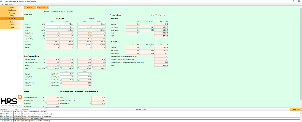
Form Fields
These are the fields and UI elements that are shown in this form, along with a describing text and explanation about their usage in the application.
Click on the Calculate button when you have the all the information completed and ready to be calculated by the server. Each click makes an API call to the server. This means that the information is sent to the server, calculated there (hence modified) and the results returned back and shown to you. Every calculation increments your license API calls counter.
Copies results from overall calculation tab to batch tab in order to calculate process batch time. Information copied are tubes mass flow, mean tubes specific heat, shell inlet temperature, shell mass flow, shell mean specific heat, area fitted and k global fouled
Declares the flow direction to be counter current, meaning that the fluid in the shell and the tubes go in opposite directions: The shell inlet is at the same side of the heat exchanger as the tubes outlet. Simmilarly, the shell outlet is at the same side as the tubes inlet.
Declares the flow direction to be co-current, meaning that the fluid in the shell and the tubes flow towards the same direction: The shell inlet is at the same side of the heat exchanger as the tubes inlet. Simmilarly, the shell outlet is at the same side as the tubes outlet.
Flow Data
Tubes Side
Shell Side
Inlet
Outlet
Inlet
Outlet
Mass flow rate of the fluid in the tubes side. Please note that, strictly speaking, in whatever chosen measurement system, seconds should be used. The application uses hours (hr) instead of seconds just for user's convenience however. Required.
Mass flow rate of the fluid in the shell side. Please note that, strictly speaking, in whatever chosen measurement system, seconds should be used. The application uses hours (hr) instead of seconds just for user's convenience however. Calculated when it is the free parameter. Required otherwise.
Bulk inlet Temperature of the fluid in the tubes side. Required.
- Metric: °C
- SI: °C
- British: °F
Bulk outlet Temperature of the fluid in the tubes side. Required.
- Metric: °C
- SI: °C
- British: °F
Bulk inlet Temperature of the fluid in the shell side. Calculated when it is the free parameter. Required otherwise.
- Metric: °C
- SI: °C
- British: °F
Bulk outlet Temperature of the fluid in the shell side. Calculated when it is the free parameter. Required otherwise.
- Metric: °C
- SI: °C
- British: °F
Duty, or Power, as the amount of energy transferred per unit time, calculated in the tubes side. Due to the Law of Conservation of Energy, this
calculated value will be equal, but with opposite sign, to the Shell:
Duty value.
- Metric: kcal/hr
- SI: kW
- British: BTU/hr
Duty, or Power, as the amount of energy transferred per unit time, calculated in the shell side. Due to the Law of Conservation of Energy, this
calculated value will be equal, but with opposite sign, to the Tubes:
Duty value.
- Metric: kcal/hr
- SI: kW
- British: BTU/hr
Mean velocity of the fluid inside the tubes considering inlet fluid properties.
Mean velocity of the fluid inside the tubes considering outlet fluid properties.
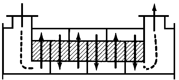
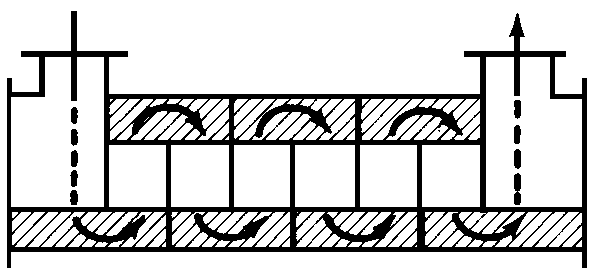
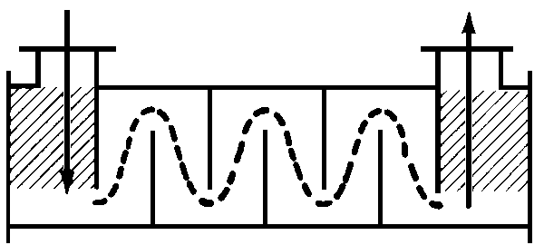
Mean velocity of the fluid on shell side considering inlet fluid properties. When no baffles or support baffles options are selected this value is the transversal velocity, considering shell cross section area. In case of full heat transfer baffles, this velocity is the cross flow velocity, taking into account cross area between baffles.
Mean velocity of the fluid on shell side considering outlet fluid properties. When no baffles or support baffles options are selected this value is the transversal velocity, considering shell cross section area. In case of full heat transfer baffles, this velocity is the cross flow velocity, taking into account cross area between baffles.
Shear rate in tubes considering inlet velocity. Shear rate is important in non newtonian fluids, increasing or decreasing apparent viscosity of the fluid.
Shear rate in tubes considering outlet velocity. Shear rate is important in non newtonian fluids, increasing or decreasing apparent viscosity of the fluid.
Shear rate in shell side considering inlet velocity. Shear rate is important in non newtonian fluids, increasing or decreasing apparent viscosity of the fluid.
Shear rate in shell side considering outlet velocity. Shear rate is important in non newtonian fluids, increasing or decreasing apparent viscosity of the fluid.
Viscosity in tube side at inlet conditions considering non-newtonian effects. If the fluid has newtonian behaviour then this value is equal to inlet viscosity value.
Viscosity in tube side at outlet conditions considering non-newtonian effects. If the fluid has newtonian behaviour then this value is equal to outlet viscosity value.
Viscosity in shell side at inlet conditions considering non-newtonian effects. If the fluid has newtonian behaviour then this value is equal to inlet viscosity value.
Viscosity in shell side at outlet conditions considering non-newtonian effects. If the fluid has newtonian behaviour then this value is equal to outlet viscosity value.
Reynolds number considering tubes inlet fluid properties and tubes geoemtry. Depending on this number we classified flow regimes. In case of one phase flow regimes are laminar, transition and turbulent.
Reynolds number considering tubes outlet fluid properties and tubes geoemtry. Depending on this number we classified flow regimes. In case of one phase flow regimes are laminar, transition and turbulent.
Reynolds number considering shell inlet fluid properties and shell geoemtry. With full baffle calculation option this value will be calculated with cross flow velocity and turbulent regimen will reach sooner. Depending on this number we classified flow regimes. In case of one phase flow regimes are laminar, transition and turbulent.
Reynolds number considering shell outlet fluid properties and shell geoemtry. With full baffle calculation option this value will be calculated with cross flow velocity and turbulent regimen will reach sooner. Depending on this number we classified flow regimes. In case of one phase flow regimes are laminar, transition and turbulent.
Prandtl number of tube fluid at inlet conditions. Prandtl number depends on thermal conductivity, heat capacity and diameter of the tube.
Prandtl number of tube fluid at outlet conditions. Prandtl number depends on thermal conductivity, heat capacity and diameter of the tube.
Prandtl number of shell fluid at inlet conditions. Prandtl number depends on thermal conductivity, heat capacity and hydraulic diameter of the shell.
Prandtl number of shell fluid at outlet conditions. Prandtl number depends on thermal conductivity, heat capacity and hydraulic diameter of the shell.
Scrapping velocity selector. For R units, it is the number of revolution per minute, and, in the case of Unicus, it is the number of cycles per minute.
For R units, it is the maximum apparent viscosity which can handle at indicated scrapping velocity.
Heat Transfer Data
Temperature of the fluid in contact with the inside wall of the tubes at inlet position.
Temperature of the fluid in contact with the inside wall of the tubes at outlet position.
Temperature of the fluid in contact with the outside wall of the tubes at inlet position.
Temperature of the fluid in contact with the outside wall of the tubes at outlet position.
Fluid viscosity at tube inlet wall temperature.
Fluid viscosity at tube outlet wall temperature.
Fluid viscosity at shell inlet wall temperature.
Fluid viscosity at shell outlet wall temperature.
Nusselt number of tubes calculated at inlet conditions. Depend mostly on Reynolds and Prandtl number.
Nusselt number of tubes calculated at outlet conditions. Depend mostly on Reynolds and Prandtl number.
Nusselt number of shell side calculated at inlet conditions. Depend mostly on Reynolds and Prandtl number.
Nusselt number of shell side calculated at outlet conditions. Depend mostly on Reynolds and Prandtl number.
On/Off
Heat transfer coefficient in tubes at inlet position.
On/Off
Heat transfer coefficient in tubes at outlet position.
On/Off
Heat transfer coefficient in shell side at inlet position.
On/Off
Heat transfer coefficient in shell side at outlet position.
It adds a resistance between inside tubes and tube wall simulating the effect of fouling in the heat exchangers between cleanings.
It adds a resistance between shell side and outside tube wall simulating the effect of fouling in the heat exchangers between cleanings.
Inlet
Outlet
Heat transfer coefficient at inlet position without considering fouling factor and calculated using appropiate(inlet or outlet) tubes and shell coefficient. Tubes inlet- Shell inlet (Cocurrent), Tubes inlet-Shell outlet (Countercurrent)
Heat transfer coefficient at outlet position without considering fouling factor and calculated using appropiate(inlet or outlet) tubes and shell coefficient. Tubes outlet - Shell outlet (Cocurrent), Tubes outlet-Shell inlet (Countercurrent)
On/Off
Heat transfer coefficient at inlet position considering fouling factor and calculated using appropiate(inlet or outlet) tubes and shell coefficient. Tubes inlet- Shell inlet (Cocurrent), Tubes inlet-Shell outlet (Countercurrent)
On/Off
Heat transfer coefficient at outlet position considering fouling factor and calculated using appropiate(inlet or outlet) tubes and shell coefficient. Tubes inlet- Shell inlet (Cocurrent), Tubes inlet-Shell outlet (Countercurrent)
On/Off
Global heat transfer coefficient considering all information of the heat exchanger.
Minimum heat transfer coefficient necessary to achieve indicated duty with the area fitted.
Areas
Minimun necessary area to achieve indicated duty in a heat exchanger considering global heat transfer coefficient.
Heat transfer area of one module with defined geometry.
On/Off
Number of modules needed to achieve temperature requirementes with defined geometry.
Total heat transfer area considering number of modules used with defined geometry.
Percentage of relative difference between area fitted and area needed
Logarithmic Mean Temperature Difference (LMTD)
LMTD #
Logarithmic Mean Temperature Difference
Multipass correction factor. In a multipass heat exchanger fluids are partially in cocurrent and countercurrent.
LMTD after apply correction factor.
Pressure Drop
Viscosity correction factor consider diferences between bulk viscosity and wall viscosity. It is important in pressure drop calculation in a heat exchanger, but if you need to calculate pressure drop in a heat exchanger like it was just a pipe you can uncheck this box.
Tubes Side
Mean velocity in tubes. This is the value used to calculate modules pressure drop.
Pressure drop considering tube lenght of all modules.
Mean velocity of fluid at tubes inlet nozzle considering tubes fluid inlet properties. This is the value used to calculate inlet nozzle pressure drop.
Rho·V^2 is a parameter used to measure cinetic energy of the fluid. If this value is too high, user should consider using protections on final heat exchanger design (ie: impigment devices).
Pressure drop at tubes inlet nozzle of all modules.
Mean velocity of fluid at tubes outlet nozzle considering tubes fluid outlet properties. This is the value used to calculate outlet nozzle pressure drop.
Rho·V^2 is a parameter used to measure cinetic energy of the fluid. If this value is too high, user should consider using protections on final heat exchanger design (ie: impigment devices).
Pressure drop at outlet nozzle of all modules.
When modules are interconnected using bends, this value is the mean velocity in that section.
Pressure drop in all interconnections between modules.
Sum of all pressure drop in tube side.
Shell Side
Mean velocity in shell side. When no baffles or support baffles calculation is activated this value consider cross section area of the shell, however, when full heat transfer baffle calculation is activated, this value will show cross flow velocity. Shell modules velocity is used to calculate shell modules pressure drop.
Pressure drop considering heat transfer zone of all modules.
Mean velocity of fluid at shell inlet nozzle considering shell fluid inlet properties. This is the value used to calculate inlet nozzle pressure drop.
Rho·V^2 is a parameter used to measure cinetic energy of the fluid. If this value is too high, user should consider using protections on final heat exchanger design (ie: impigment devices).
Pressure drop at shell inlet nozzle of all modules.
Mean velocity of fluid at shell outlet nozzle considering shell fluid outlet properties. This is the value used to calculate outlet nozzle pressure drop.
Rho·V^2 is a parameter used to measure cinetic energy of the fluid. If this value is too high, user should consider using protections on final heat exchanger design (ie: impigment devices).
Pressure drop at shell outlet nozzle of all modules.
Pressure drop calculated using Bell Delaware method. This value represent the pressure drop in central baffle space of all modules needed. It Will be zero when full heat transfer baffle option is desactivated
Pressure drop calculated using Bell Delaware method. This value represent the pressure drop in window section of baffles of all modules fitted. It will be calculated always when the design includes baffles.
Pressure drop calculated using Bell Delaware method. This value represent the pressure drop in entrance and exit zone of baffle all modules fitted. It Will be zero when full heat transfer baffle option is desactivated
Sum of all pressure drop in shell side.